
Professional guide to diagnosing irrigation electrical connections. Covers multimeter testing, waterproof connector failures, and field wiring troubleshooting for reliable sprinkler systems.
When irrigation zones stop working, the culprit isn't usually mechanical failure or bad valves. It's electrical connections failing underground where you can't see them deteriorating. Wiring connections cause roughly 70% of all irrigation system failures, and most of these problems trace back to one issue: waterproof wire connectors that weren't actually waterproof.
This troubleshooting guide covers systematic electrical diagnosis using multimeter testing, identifying the three types of connection failures that kill irrigation systems, and proven repair techniques that prevent callbacks. Whether you're chasing a single dead zone or multiple system failures, these diagnostic steps will pinpoint the problem fast.
Need connectors that handle irrigation valve box conditions?
Our UL486D rated silicone-filled connectors resist moisture, soil chemistry, and temperature cycling for reliable underground connections.
Understanding Irrigation System Electrical Anatomy
Professional irrigation troubleshooting starts with understanding how electricity flows through the system. The basic electrical anatomy involves three main components: the controller, the field wiring and the electric solenoid valves, with 24V AC signals traveling from controller to valve and back through the common wire.
Why 70% of Irrigation Failures Are Electrical
Standard wire nuts not intended for irrigation use create corrosion when wet, leading to the resistance problems that show up as dead zones, intermittent operation, or complete system failures. Understanding this helps focus troubleshooting efforts where problems actually occur.
Critical connection points that fail:
- Valve box splices – Where controller wires connect to solenoid leads
- Direct burial connections – Hidden splices between valve boxes
- Controller terminal strips – Loose connections at the control panel
- Solenoid connections – Wire attachments to valve solenoids
Each connection point creates resistance in the 24V circuit. When resistance gets too high from corrosion or poor connections, solenoids stop operating reliably.
The 20–60 Ohm Rule for Irrigation Circuits
Normal irrigation circuits test between 20 and 60 ohms resistance when measured from the controller common to the station wire. This range indicates healthy wiring and functional solenoids working together.
What different resistance readings tell you:
- 20–60 ohms – Normal circuit operation
- Below 20 ohms – Short circuit (wires touching, damaged solenoid)
- Above 60 ohms – High resistance (corroded connections, failing solenoid)
- Infinite / OL – Open circuit (broken wire, disconnected splice)
These resistance patterns guide diagnostic decisions and help identify whether problems exist in wiring, connections, or solenoids themselves.
Professional Multimeter Testing Techniques
A decent multimeter can be purchased for less than $20 and is critical to the troubleshooting process. Systematic testing eliminates guesswork and identifies electrical problems quickly without unnecessary digging.
Step 1: Controller Voltage Testing
Start with the controller since all electrical signals originate there. Poor controller output creates symptoms that look like field wiring problems.
Testing controller output:
- Turn on the problem zone manually at the controller
- Set multimeter to AC voltage setting (VAC)
- Connect probes – one to zone terminal, one to common terminal
- Reading should be 24–28 volts AC
If the reading is outside the acceptable range, replace the controller. Good voltage output means the problem lies in field wiring or valve components.
Step 2: Circuit Resistance Testing
Turn OFF the station and/or the entire controller when testing for ohms (resistance) to avoid false readings and potential multimeter damage.
Resistance test procedure:
- Power down controller completely
- Disconnect station wire from controller terminal
- Set multimeter to ohms/resistance setting (Ω)
- Connect probes – black to common terminal, red to disconnected station wire
- Normal reading – 20–60 ohms
Interpreting resistance results:
- If resistance is below 20 ohms (a short), disconnect the solenoid from the field wires and test the solenoid separately to determine if the short is in the solenoid or field wiring.
- If resistance is above 60 ohms (high/open), test the solenoid without the field wires connected. High resistance usually indicates corroded connections or failing solenoids.
Step 3: Valve Box Diagnosis
When controller testing shows good voltage but poor resistance readings, the problem exists between controller and valve. This requires testing at the valve box to isolate the issue.
Field testing process:
- Locate valve box for the problem zone
- Test voltage at valve – should match controller output
- Disconnect solenoid wires from field wiring
- Test solenoid resistance directly across solenoid terminals
- Compare readings to eliminate variables
If the solenoid tests within proper limits of between 20–60 ohms and the circuit resistance was high, then the problem was a faulty wire connector.
Identifying the Three Types of Connection Failures
Irrigation electrical problems fall into three distinct categories, each with specific symptoms and resistance signatures that guide repair decisions.
Short Circuits (Below 20 Ohms)
Short circuits occur when electricity takes an unintended path back to the controller, bypassing the solenoid or creating parallel paths that draw excessive current.
Common causes of shorts:
- Damaged solenoids with internal coil failures
- Wire insulation failure allowing bare conductors to touch
- Flooded valve boxes where exposed splices contact each other
- Multiple solenoids connected to single station (lowers total resistance)
With a short, the current will be taking a "shortcut" back to the controller; therefore, you will get a low ohm reading, somewhere around 1–10 ohms.
Troubleshooting short circuits: Test solenoids individually by disconnecting field wiring and measuring resistance across solenoid terminals only. If the solenoid tests normal, the short exists in field wiring or connections.
Open Circuits (Above 60 Ohms or Infinite)
Open circuits prevent electrical current from completing its path, resulting in zones that won't activate regardless of controller commands.
Typical open circuit problems:
- Broken wires from digging damage or root pressure
- Corroded splices that lose electrical continuity over time
- Disconnected terminals at controller or solenoid
- Failed solenoids with burnt-out coils
With this type of problem the current from the meter has no way of returning to the meter because of the break. So you will get an "Infinity" reading.
Locating open circuits: Cut out the wire connectors and connect the station and common wires together at the valve location. From the controller, re-test the resistance without the solenoid in the circuit. If resistance drops to near zero, the problem is corroded connections.
High Resistance (Marginal Connections)
High-resistance connections create intermittent problems that worsen over time as corrosion progresses. These are often the most frustrating to diagnose because they work sometimes.
Signs of high resistance problems:
- Intermittent zone operation – works some days, not others
- Voltage drop under load that prevents solenoid activation
- Temperature sensitivity – works in cool weather, fails when hot
- Progressive failure – gradually gets worse over months
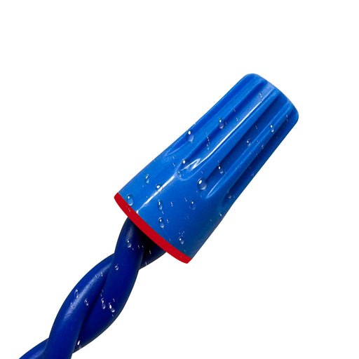
When moisture penetrates that connection, you can get an open circuit. The water and moisture will start to wick between the conductor and the insulation of the wire, which leads to corrosion.
Waterproof Connection Requirements for Irrigation Systems
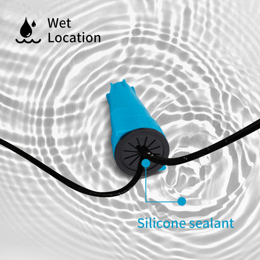
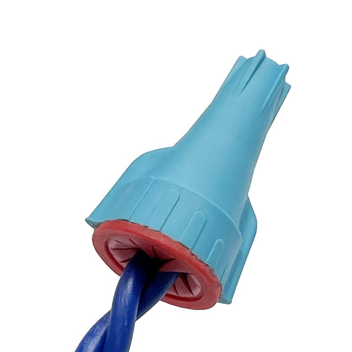
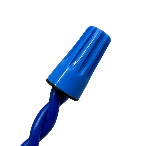
Waterproof wiring connectors should be used on all irrigation wire connections that are underground or in any environment that could become wet. Standard indoor wire nuts fail rapidly when exposed to moisture and soil chemistry.
Why Standard Wire Nuts Fail in Valve Boxes
Standard wire nuts are made of two different metals. When wet, these metals react with each other and corrosion results. This galvanic corrosion process accelerates in the moist conditions typical of irrigation valve boxes.
Environmental challenges for valve box connections:
- Seasonal flooding from rain and irrigation overspray
- Soil chemistry including fertilizers and treatment chemicals
- Temperature cycling causing expansion and contraction
- Root intrusion creating mechanical stress on connections
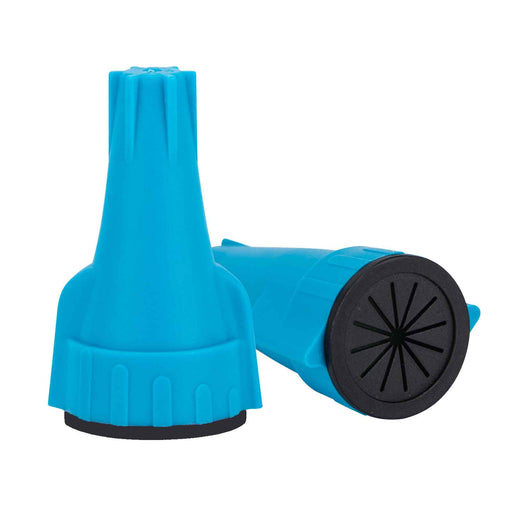
Professional installations require waterproof wire connectors specifically designed for irrigation use rather than generic outdoor products.
Silicone-Filled vs Gel-Filled Connectors
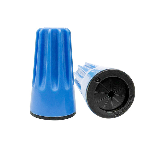
Wire connectors filled with silicone, gel, or grease create a waterproof connection, which is ideal for underground connections in a valve box. However, the type of sealant affects long-term reliability significantly.
Advantages of silicone-filled connectors:
- Temperature stability – maintains protection from -40°F to 221°F
- Chemical resistance – won't break down from fertilizer exposure
- Permanent adhesion – bonds to housing walls without migration
- Electrical integrity – superior dielectric strength prevents shorts
Problems with petroleum gel alternatives:
- Temperature sensitivity – becomes liquid in heat, brittle when cold
- Chemical degradation – dissolves when exposed to lawn chemicals
- Migration issues – separates from connections over time
- Contamination potential – can become conductive when mixed with dirt
For comprehensive technical specifications and performance testing data, see our Complete Waterproof Wire Connector Installation Guide.
Field Repair Techniques That Prevent Callbacks
Successful irrigation repairs require proper materials and installation techniques that address the root causes of connection failures rather than temporary fixes.
Valve Box Connection Repair
Install new waterproof wire connectors on the existing solenoid and test the resistance again at the controller. This systematic approach ensures repairs actually solve the underlying problem.
Professional repair process:
- Remove old connections completely – cut back to clean copper
- Strip wires to manufacturer specifications (typically 1/2 inch)
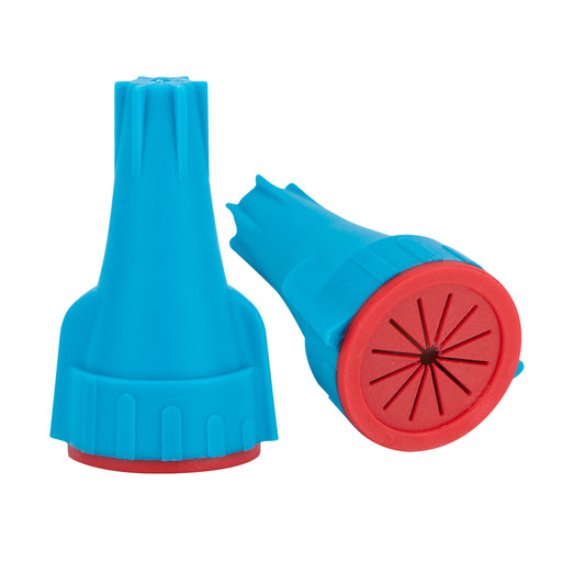
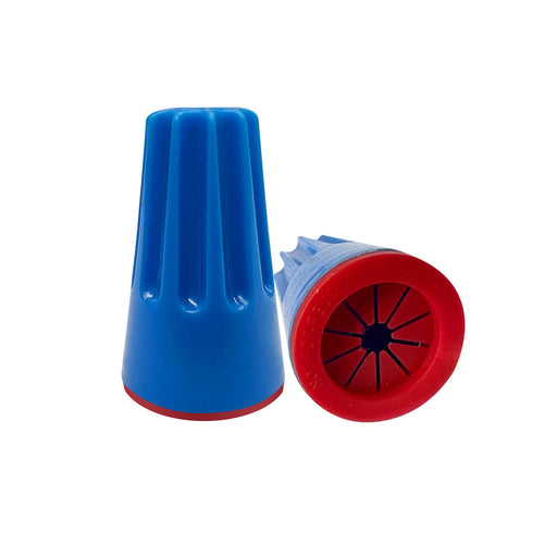
- Install UL486D rated waterproof connectors designed for direct burial
- Secure connections away from standing water when possible
- Test resistance from controller before backfilling
Avoiding common repair mistakes:
- Don't reuse corroded connectors even if they look salvageable
- Never use indoor wire nuts as temporary fixes in valve boxes
- Avoid petroleum gel products that migrate away from connections
- Don't skip multimeter testing to verify successful repairs
Underground Splice Repairs
Bad connections are often buried and can only be found with a ground fault detector. When splices fail between valve boxes, systematic testing identifies the general location before excavation.
Locating hidden connection failures:
Use resistance testing at multiple valve boxes to narrow down problem areas. If zone 3 tests normal at the controller but shows high resistance when tested at valve box 3, the problem exists between the controller and that valve box.
Professional underground splicing:
- Use only UL486D rated direct burial connectors
- Provide mechanical protection with junction boxes where possible
- Mark splice locations for future reference and maintenance
- Test thoroughly before backfilling to avoid re-excavation
Systematic Troubleshooting Workflow
Professional irrigation diagnosis follows a logical sequence that eliminates variables and identifies root causes efficiently.
The Three-Component Diagnostic Method
There are three areas to check when investigating the electrical part of the system: the controller, the field wiring, and the electric solenoid valves. Testing in sequence prevents wasted time chasing symptoms instead of causes.
Step-by-step diagnostic process:
-
Controller testing (5 minutes)
- Verify 120V input power to controller
- Test 24V AC output to problem zone
- Check other zones for comparison
- Replace controller if voltage output fails
-
Circuit resistance testing (5 minutes)
- Power down controller completely
- Disconnect station wire from controller
- Measure resistance between station and common wires
- Compare readings to 20–60 ohm normal range
-
Field investigation (15–30 minutes)
- Locate valve box for problem zone
- Test voltage at valve – should match controller output
- Test solenoid resistance independently
- Compare solenoid and circuit readings to isolate the problem
When to Replace vs Repair Connections
Replace connections when:
- Resistance readings are outside 20–60 ohm range
- Visible corrosion exists on copper conductors
- Petroleum gel connectors show signs of migration
- Multiple zones share connection points that test poorly
Simple repairs work when:
- Loose terminal connections at controller
- Clean copper with adequate wire length available
- Solenoids test normal when disconnected from field wiring
- Problem isolated to a single connection point
Frequently Asked Questions About Irrigation Electrical Problems
What does it mean when my multimeter shows infinite resistance on an irrigation zone?
Infinite resistance (often displayed as "OL" or "1") indicates an open circuit somewhere between the controller and solenoid. This could be caused by a broken wire, a disconnected splice, or a completely failed solenoid. Test the solenoid directly at the valve to determine if the break exists in field wiring or the solenoid itself.
Why do some irrigation zones work intermittently?
Intermittent operation usually indicates high-resistance connections that work when cool but fail when resistance increases with temperature. When moisture penetrates connections, water and moisture will start to wick between the conductor and insulation, which leads to corrosion that creates intermittent electrical contact.
What causes irrigation controller fuses to blow repeatedly?
If the fuse has been blown, the most likely reason is a field wiring short. Short circuits draw excessive current that trips protection devices. Locate the short by testing individual zones for resistance below 20 ohms, then isolate whether the short exists in solenoids or field wiring.
Can I use regular wire nuts in irrigation valve boxes?
No, regular wire nuts lack the moisture protection needed for valve box environments. Standard wire nuts are made of two different metals that react with each other when wet, causing corrosion. Use UL486D rated waterproof connectors specifically designed for irrigation applications.
What should I do if multiple irrigation zones stop working at once?
Test the common wire connection first, as it serves all zones. If only one or maybe a select few areas of your irrigation system are turning on, you can verify this with a multimeter by placing one probe on your white common wire and the other on each zone. A broken common wire creates symptoms that affect multiple zones simultaneously.
How do I test if my irrigation solenoid is bad?
Disconnect the solenoid from field wires and test resistance directly across solenoid terminals. The reading should be between 20–60 ohms. Readings outside this range indicate solenoid failure requiring replacement.
What's the difference between UL486D and UL486G for irrigation connections?
Both UL486D and UL486G now cover direct burial applications for irrigation systems as of July 2024 updates. UL486D provides superior protection for harsh conditions like aggressive soil chemistry or continuous submersion, while UL486G handles most standard irrigation installations effectively.
Why does my irrigation system work fine in winter but fail in summer?
Temperature affects electrical resistance — high resistance connections that work in cool weather may fail when heat increases resistance further. Poor connections create voltage drop under load that prevents solenoid activation when resistance increases with temperature.
Professional Prevention: Building Reliable Irrigation Electrical Systems
The key to avoiding irrigation electrical failures lies in proper initial installation and using components designed for underground moisture exposure.
Waterproof Connection Standards
- UL486D or UL486G certification for direct burial applications
- Silicone-filled sealant chambers that resist temperature and chemical exposure
- Proper wire preparation with clean copper and correct strip lengths
- Mechanical protection through junction boxes or burial depth
Long-term Reliability Factors
Component selection:
- Choose certified waterproof connectors over generic alternatives
- Use connectors with adequate wire gauge capacity for applications
- Select products with temperature ratings exceeding local climate extremes
Installation quality:
- Follow manufacturer strip length specifications exactly
- Ensure complete wire insertion into connector chambers
- Position connections away from standing water when possible
- Mark connection locations for future maintenance access
Maintenance planning:
- Schedule annual electrical testing during system startup
- Replace petroleum gel connectors during routine valve service
- Upgrade questionable connections before they fail completely
Need waterproof connectors that handle irrigation conditions?
Our UL486D rated silicone-filled connectors resist moisture, soil chemistry, and temperature cycling for reliable irrigation valve connections.